The Missing Umbrella
EGR314 Team 205 - Deepit Arora, Enoch Choi, Michael Gross
Project maintained by EGR314-Team205 Hosted on GitHub Pages — Theme by mattgraham
Table of Contents
- Mission Statement
- Innovation Showcase Poster
- Team Design
- Block Diagram
- Component Selection
- Hardware Implementation
- Software Implementation
- Lessons Learned
- Recommendations For Future Students
- Initial Design Brief
- Appendix
Mission Statement
“Our mission is to design and develop an embedded system that incorporates environmental sensors, providing users with real-time data on temperature and wind speed. By leveraging affordability and small form-factor technologies, we strive to deliver a product that will benifit the user and exceed their expectations.”
Innovation Showcase Poster

Team Design: Weather Umbrella
This is a product that will assist people in wheelchair to block the wet rain or the very hot sunlight. This device will be activated when either the temperature detects very hot weather or the user feels rain coming down. When it rains, the wind speed sensor will use the data collected of the wind speed and calculate the direction of the wind to direct the umbrella to go against the rain the protect the user from getting wet. The umbrella that is mounted in this device is a umbrella that is able to open and close with a push of a button which will be pressed by the solenoid motor. Also, there is a clamp at the bottom of the device that will be able to clamp onto the side poles of the back supports of wheelchairs.
Final Design (Innovation Showcase)

Design Rationale
During the decision-making process for our selected design, we realized that the initial three ideas did not fully meet the requirements of the course project, nor did they demonstrate the functionality of our project as we had hoped. To address this, we brainstormed new ideas and agreed to use the temperature sensor and hall effect sensor, given their compatibility and our prior experience with testing them. Ultimately, we settled on the innovative concept of a weather umbrella assistant for wheelchairs.

Project Idealization
Rendered Idealistic Design

Render of PCB Holder

Render of Team PCB

Render of Umbrella Holder

Block Diagram
The following illustration demonstrates the team’s projected hardware system and how it interconnects with the centered microcontroller and ESP32 Module. Additionally, the team utilizes I2C as the core communication between our sensors and PIC module.

Component Selection Overview
Motor Subsystem
| Solution | Image |
|---|---|
| Motor Driver (DRV8830DGQR) | 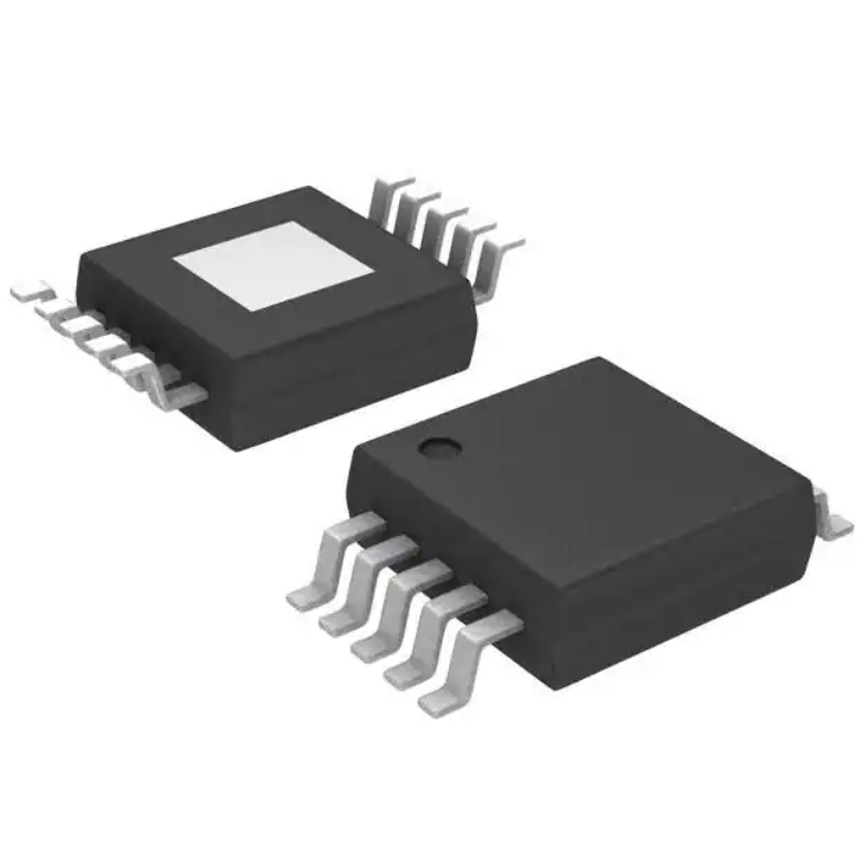 |
| Adafruit 5V Solenoid | 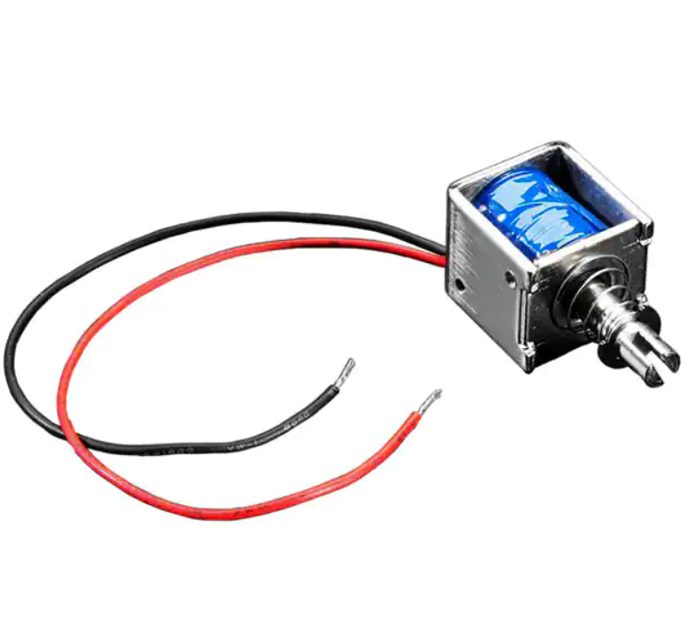 |
| Pololu 84 RPM 6V Micro Gearmotor | 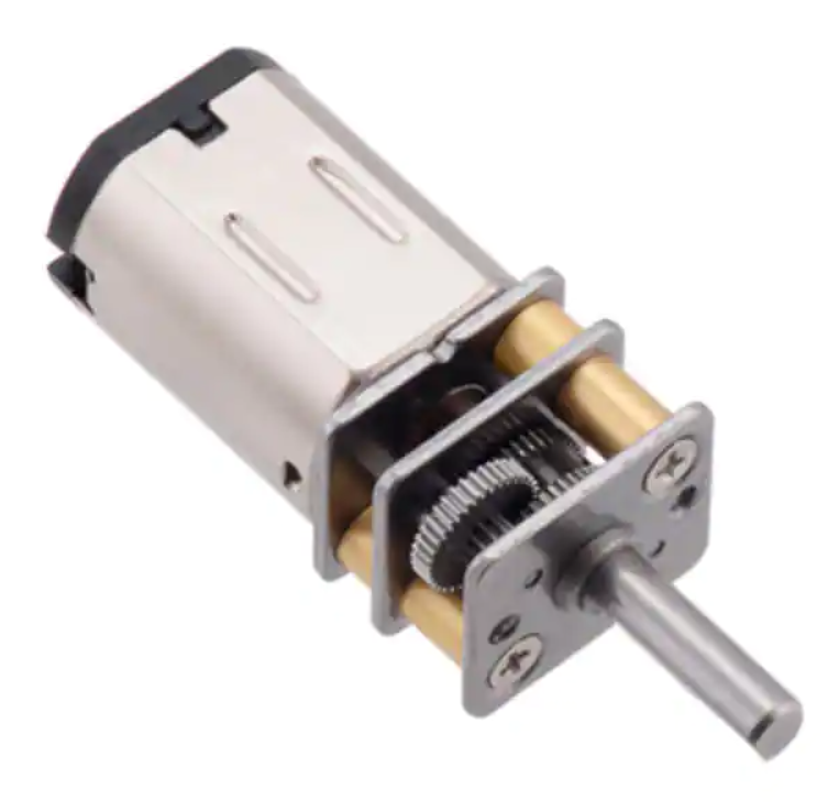 |
Temperature Sensor
| Solution | Image |
|---|---|
| TC74A4 | 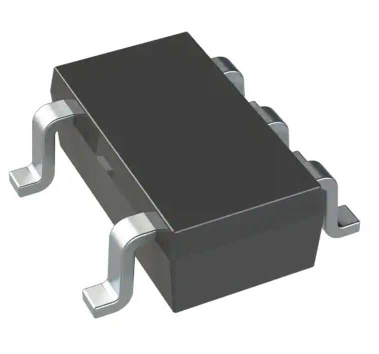 |
Hall Effect Sensor (Wind Speed Subsystem)
| Solution | Image |
|---|---|
| AS5600 | 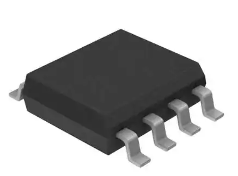 |
Microcontroller
| Solution | Image |
|---|---|
| PIC18LF26K40 | 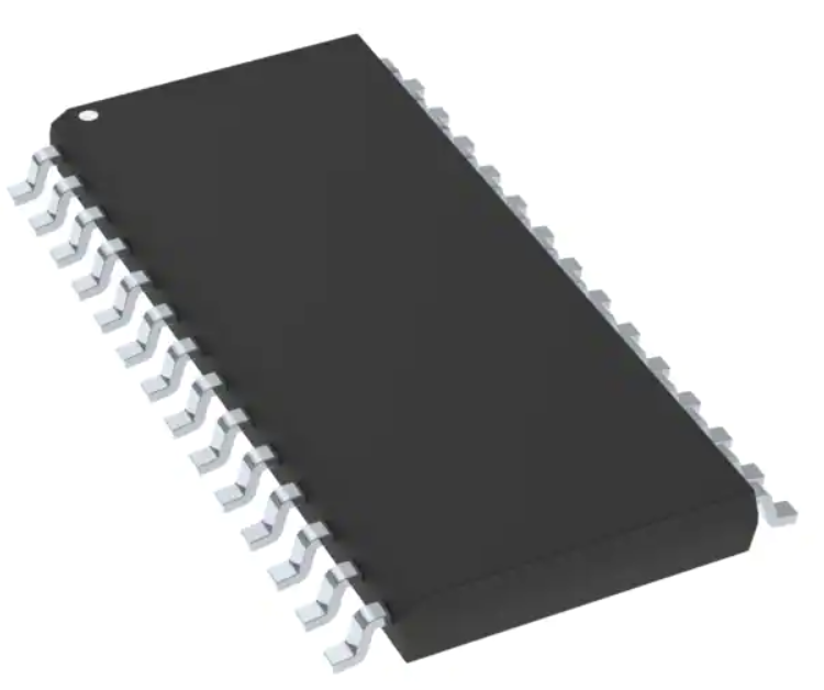 |
Refer to Appendix E for more information
Hardware Implementation
The following is the schematic for our team PCB


Check Appendix H - Hardware Proposal for more information
PCB Renders
Team PCB


Daughter Board


Future Hardware Design Changes
In the development of our embedded systems project, it is crucial to carefully consider the power budgeting of the system. Our design currently relies on a wall power system but will need to rely on a standalone battery supply in our proposed application. With this said, It is imperative to evaluate ways in which power budgeting can be made more efficient. One approach that our team can consider, although slightly over the top, is the utilization of enable pins that can be controlled by unused pins from the microcontroller. Such power-saving techniques can extend the battery life of the system. Furthermore, more advanced methods, such as reducing power consumption during idle periods or implementing sleep modes, can also be explored.
Optimizing the hardware design is another important aspect to improve the performance and reliability of the system by utilizing more efficient hardware configurations. For instance, passive components packages (0805) can be standardized internally and avoid smaller IC packages as our motor controller was non-functional due to potential hardware issues with installation.
Leaving room for expansion and adaptability is an important quality to have when manufacturing. Additional sensors or hardware components can be easily added through connection pins and designing the software architecture to allow for easy modification. The potential for modularized sensor systems, such as atmospheric and humidity sensors, was discussed during the innovation showcase and should be considered for future development.
By taking into account these areas of improvement, our team can create a more efficient and reliable mobile weather station and the above changes can be implemented to ensure the system is adaptable for future versions.
Software Implementation
Our software proposal outlines the steps for the program to effectively operate. It begins by initializing all sensors and drivers and establishing a secure connection with each of them. The program then monitors sensor values and compares them with predefined thresholds to determine the appropriate actions, including controlling the motors. By following these steps, our software will enable smooth and reliable operation of the system.
Check Appendix G - Software Proposal for more information

MPLABX Peripheral Overview
See the following figures for the peripherals and pin GPIO structure utilized in the MPLAB Code Configurator


Topic Table
Below is our table summarizing all the published and subscribed messages for our topic:

Feedback Controller Diagram
Below is our feedback controller diagram which outlines the simplistic software loop to actuate our motors based on measured sensor data

Future Software Design Changes
The current system uses an OLED screen for displaying data via bar charts. Adding additional user interface elements on top of our button, such as more complex read-only ESP32 commands, would allow the user for more interactivity and control.
The code performance can be optimized for smaller-scale embedded systems such as these which have minimal processing energy and memory. Utilizing simpler functions, algorithms, and smaller data types will reduce memory usage and optimize the overall hardware platform. Small changes such as declaring constant variables and reducing utilization of global variables will also create a better performance impact.
Given that our microcontroller only has 10kb of programmable memory, we could consider writing data to an onboard SD card if more peripherals and sensors were added to the system. With our current design, we were exceeding 90% capacity so external memory could be a valid option. The PIC Microcontrollers have slower processing speeds so utilizing interrupt service protocols (ISP) in our code algorithms will significantly improve performance and reduce the apparent lag of our single-threaded code capacity.
Lessons Learned
- Label components with their values on the schematic to help with organization and board populating.
- Be specific about sensor values in software proposals.
- When selecting a microcontroller, carefully read the specifications to ensure it has the necessary capabilities for the project.
- Update project files as changes are made to facilitate understanding by peers.
- Communication is critical in group projects to stay on track and ensure tasks are completed.
- Organize the software diagram logically for clarity.
- Use indicator LEDs on subsystems to test their functionality during PCB board population.
- Order multiples of components in case of breakage or loss.
- Keep track of deadlines and create a schedule for the team.
- Complete assignments beforehand for time to review and fix errors before submission.
Recommendations for Future Students
- Pay close attention to details and be precise in your work, especially when it comes to labeling components and specifying values.
- Communication is key to success in group projects, so make sure to keep in touch with your team regularly.
- Keep your project files organized and updated to make it easier for peers to understand your work.
- When selecting components, be sure to order multiples in case of loss or breakage.
- Follow a schedule and keep track of deadlines to avoid rushing work.
- Review and double-check your work before submission to catch any errors or mistakes.
- Breaking larger assignments into smaller tasks and setting deadlines for each one.
- Identifying potential obstacles or conflicts ahead of time and coming up with strategies to address them.
- Implementing feedback from the teaching team in a timely fashion.
Initial Design Brief (Checkpoint 1)

Appendices
Appendix A - Team Organization
Appendix B - User Needs, Benchmarking, and Requirements
Appendix B - User Needs, Benchmarking, and Requirements
Appendix C - Design Ideation
Appendix D - Verification Table
Appendix D - Verification Table
Appendix E - Component Selection
Appendix E - Component Selection
Appendix F - Microcontroller Selection
Appendix F - Microcontroller Selection
Appendix G - Software Proposal
Appendix G - Software Proposal